|
Instruction
Manual
CT100 Stereo
Phono Stage Module
|
Make
sure to read the COMPLETE Instruction Manual before connecting
CT100. | |
CONNECTIONS
Definitions
Please see the text
on the PC board.
|
Marking |
Definition |
|
IN
1 |
Signal input, channel
1 |
|
IN
2 |
Signal input, channel
2 |
|
OUT 1 +/- |
Signal output, channel 1
(Bal./Unbal.) |
|
OUT 2 +/- |
Signal output, channel 2
(Bal./Unbal.) |
|
GND |
Ground, channel 1 |
|
GND |
Ground, channel
2 | |
The power supply
must be connected to both 3-way PCB square pin
headers:
Figure 1.
Power supply connections.
Electrical connections
The power
supply must be connected in accordance with fig. 1. (See also POWER
SUPPLY).
The signal output must be connected with screened
cables. The (braid/foil) screens must be soldered to the flat connector
tabs (~spade terminals) and the center conductors (cores) must be
soldered to the PCB round pin terminals. The marking on the PC board shows
this. The signal output can provide balanced or unbalanced signals. See
fig. 2 and fig. 3.
Figure 2.
Unbalanced output
connections.
 Figure 3. Figure 3.
Balanced output
connections.
|
WARNING!
Avoid
shortcircuting any of the outputs (+ or - outputs) to ground.
Also avoid connecting + and - outputs directly to each other.
Doing so will
damage the output
devices. | |
The
signal input must be connected to the phono transducer/cartridge. If
the cartridge is wired with screened cables, the screens must be soldered
to the flat connector tabs and the center conductors must be soldered to
the PCB round pin terminals IN 1/2. If the cartridge is wired with
unscreened wires, then take care that the wires are not interchanged,
which will cause inverting of the phase of one or both channels. Likewise,
take care that Right and Left channels are not interchanged. See fig.
4 and fig. 5.
|
|
|
Fig.
4. Connecting the cartridge using screened cables.
|
|
|
|
Fig.
5. Connecting the cartridge using unscreened wires.
|
|
| |
GND.
The two round GND pin terminals must be connected with short wires to the
solder tags on the attached Screen Plate P117-02. This is normally done by
the manufacturer before shipping. Please observe that no conductor tracks
on the PC board unintendedly connect to the Screen Plate or other external
circuits. See fig. 6. (See also MOUNTING).
Mechanical mounting
The CT100 PC
board must be mounted on the Screen Plate P117-02. Normally this is done
by the manufacturer. (See also MOUNTING).
Dual-mono
CT100 is only
operating in true dual-mono when the two channels are connected to two
individual power supplies. This is recommended. (It is possible to power
supply both channels with only one power supply, but this is not true
dual-mono. See also POWER
SUPPLY).
Headphones
If headphones are
connected directly to CT100, there is a risk of overloading the output
devices and thereby affecting the reliability of CT100. Headphones are
normally not connected directly to CT100. (OUT 1 and OUT 2 are intended to
be connected to a preamplifier). If headphones are experimentally
connected to CT100, the volume can be adjusted with Gain. (See also SETTINGS).
We recommend to use dynamic headphones with an impedance of 600 Ohms or
higher. Use terminals marked OUT 1 and OUT 2. Take care that the phase is
correct and that Right and Left channels are not interchanged. Both
channels are connected in the same way: The 0 (normally a screen) is
connected to the flat connector tab and the other conductor (normally a
single core) is connected to the round pin terminal +". (To invert the
phase, use the round pin terminals -).
|
WARNING!
Avoid playing with
the headphones at so loud volume that extended listening may
affect your
hearing. | |
In
order to reduce the risk of excessive power dissipation in the output
devices of CT100, the power supply voltage must
not exceed ±24 Volts with headphones connected directly to CT100.
POWER SUPPLY
Definitions
See CONNECTIONS
fig. 1.
Power
requirements
CT100 must be supplied with a ±DC voltage, which
is a positive voltage with reference to 0 Volts (Common) as well as a
negative voltage with reference to the same 0 Volts. The positive and
negative voltages are usually of equal magnitude. Although equal magnitude
is not required it is recommended. Each channel of CT100 provides local
positive and negative voltage regulation of ±16 Volts when CT100 is power
supplied with ±17 Volts to ±35 Volts. CT100 can operate with minimum ±9
Volts. When CT100 is connected to a preamplifier or a loading impedance
higher than 5 kOhms, the power supply requirement is:
When CT100 is connected to a loading
impedance lower than 5 kOhms, the power supply requirement is:
The supply current is approx. ±22mA per
channel, but possibly higher when the loading impedance is less than 5
kOhms, depending on the audio signal level.
|
WARNING!
If the CT100 is
power supplied incorrectly with only a positive voltage or
only a negative voltage, a DC voltage of several Volts will
occur on the output terminals OUT 1 and OUT
2. | |
In
other words this means if only one (+ or -) voltage is connected to the
CT100, a DC voltage and/or an AC voltage of unacceptable magnitude will
occur on the output of CT100. Probably harmless to CT100, but connected
hi-fl equipment etc. could be damaged. Especially if this equipment can
amplify DC voltage and thereby destroy loudspeaker voice coils and set
them on fire. The user is solely responsible that the power requirements
are observed and followed correctly. (We believe that power amplifiers
should not be able to amplify DC voltage).
CT100-pow1 mains adapters (CT100
accessory).
 You may purchase the DACT CT100-pow1 mains
adapters/power supplies for powering your CT100. Although not the ideal
power supply, CT100-pow1 is a good, convenient and safe power source for
CT100. We recommend using two CT100-pow1's - one for each channel. In this
way CT100 can be operated in true dual-mono. When connecting the
CT100-pow1's to the mains make sure that their input voltage and input
frequency range are correct for your local mains power supply before they
are connected to the mains socket. Europe: (23OVAC/5OHz). The mains
adapters are regarded as safe. (Approvals: CE/N/SD/Fi and more. Safety
standards: HD 195 56. EN 60950). Each mains adapter provides stabilised DC
voltage of ±23 Volts. The marking indicates ±17 Volts. This valids for a
loading of (70mA). When connected to CT100, each adapter will provide
approx. ±20 Volts. The leads on both mains adapters are terminated with a
3-way 0.1 inch locking connector which fit onto CT100. These connectors
are designed to ensure locking and correct polarizing when connected to
the CT100 power supply input sockets. For the sake of optimized sonic
performance (based on subjective evaluation) and in order to minimize
mains leakage into ground circuit, the correct "Phase" is indicated on the
mains adapters. See fig. 7. The mains power supply live wire "Phase" can
be identified in the mains socket with a mains tester (neon indicator).
DANGER! Electric shock risk! The mains high voltage is dangerous! Although
Phase" is recommended to be connected according to fig. 7 this is not
required for CT100 to function, but the recommended connection of
"Phase" will optimize the sonic performance. You may purchase the DACT CT100-pow1 mains
adapters/power supplies for powering your CT100. Although not the ideal
power supply, CT100-pow1 is a good, convenient and safe power source for
CT100. We recommend using two CT100-pow1's - one for each channel. In this
way CT100 can be operated in true dual-mono. When connecting the
CT100-pow1's to the mains make sure that their input voltage and input
frequency range are correct for your local mains power supply before they
are connected to the mains socket. Europe: (23OVAC/5OHz). The mains
adapters are regarded as safe. (Approvals: CE/N/SD/Fi and more. Safety
standards: HD 195 56. EN 60950). Each mains adapter provides stabilised DC
voltage of ±23 Volts. The marking indicates ±17 Volts. This valids for a
loading of (70mA). When connected to CT100, each adapter will provide
approx. ±20 Volts. The leads on both mains adapters are terminated with a
3-way 0.1 inch locking connector which fit onto CT100. These connectors
are designed to ensure locking and correct polarizing when connected to
the CT100 power supply input sockets. For the sake of optimized sonic
performance (based on subjective evaluation) and in order to minimize
mains leakage into ground circuit, the correct "Phase" is indicated on the
mains adapters. See fig. 7. The mains power supply live wire "Phase" can
be identified in the mains socket with a mains tester (neon indicator).
DANGER! Electric shock risk! The mains high voltage is dangerous! Although
Phase" is recommended to be connected according to fig. 7 this is not
required for CT100 to function, but the recommended connection of
"Phase" will optimize the sonic performance.
Note: The
CT100-pow1 mains adapters are not suitable as battery chargers.
|
WARNING!
The mains adapters
are for indoor use only! Do not expose the units to water,
rain or dust. They must not be covered over. Do not remove the
casings. | |
Other
power supplies
If CT100 is installed in units having their own
±DC voltage power supply, CT100 can be connected to the units DC voltage
if all above-mentioned power requirements are met including the ability to
supply at least ±22mA per channel.
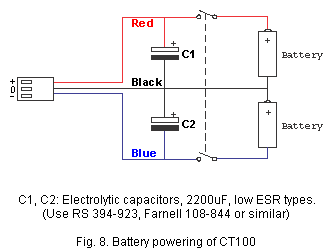
Battery
powering
 Powering with batteries or rechargeable
batteries nearly always change the subjective evaluation of the sonic
performance compared to powering by the supplied mains adapters. The user
must decide for himself, which is preferred as "correct". For reference
use, battery power supply is recommended to ensure uniform power
conditions from test to test and to eliminate mains leakage into ground
circuit. All above-mentioned power requirements are valid for battery
powering as well. Rechargeable batteries may be used as well, but a mains
powered charging circuit will induce mains leakage into the ground circuit
of the hi-fl system. Such charging circuits should be disconnected from
the mains when the charging is ended in order to assure all advantages of
battery powering. Each CT100 is supplied with two cables terminated with
locking connectors intended for connecting CT100 to batteries or other
power sources. The three cores are colour coded in accordance with fig. 1.
(See CONNECTIONS).
See also fig. 8. Powering with batteries or rechargeable
batteries nearly always change the subjective evaluation of the sonic
performance compared to powering by the supplied mains adapters. The user
must decide for himself, which is preferred as "correct". For reference
use, battery power supply is recommended to ensure uniform power
conditions from test to test and to eliminate mains leakage into ground
circuit. All above-mentioned power requirements are valid for battery
powering as well. Rechargeable batteries may be used as well, but a mains
powered charging circuit will induce mains leakage into the ground circuit
of the hi-fl system. Such charging circuits should be disconnected from
the mains when the charging is ended in order to assure all advantages of
battery powering. Each CT100 is supplied with two cables terminated with
locking connectors intended for connecting CT100 to batteries or other
power sources. The three cores are colour coded in accordance with fig. 1.
(See CONNECTIONS).
See also fig. 8.
CT100
voltage regulators
CT100 has 4 voltage regulators on
board. Each of the two channels has one positive and one negative voltage
regulator. All voltage regulators consist of two independent sections in
series. Four ferrite bead filters provide effective RFI suppression.
(Mobile phones etc.). Decoupling capacitors are selected to ensure optimum
wideband working conditions for audio signals.
MOUNTING
Noise
sources
Phono amplifiers are very sensitive and mostly
screening is required. When CT100 is installed, it is advisable to make
experiments with wiring and screening if noise interference occurs. The
following directions are guidelines. They apply for dual-mono and balanced
output unless otherwise specified.
Common noise sources
-
Transformers
- Electrical motors
- Mobile phones
- Relays
-
Electrical appliances
Screen
Plate P117-02
The Screen Plate must always be
used even if CT100 is built into a metal box. It provides RF shielding,
protects the SMD components on the rear side of the PCB and avoids that
PCB tracks are short-circuited accidentally. CT100 is normally shipped
mounted on its Screen Plate.
Mounting into turntables
CT100
can be built into a turntable so that the sensitive audio signal from the
cartridge can be wired to CT100 with short wires or screened cables in
order to protect the original audio signal from noise interference. This
configuration enables the turntable to deliver a balanced (2 Volts) or
unbalanced (1 Volt) audio signal directly to preamplifiers etc. Fig. 10
shows installation into a non-metal enclosure/turntable. Follow
1-9:
1. Draw the complete circuit diagram of the turntable. Keep
it.
2 . Fix CT100 near the signal from the cartridge and far
away from motor, mains transformer etc.
3. Connect (solder) GND
on both channels to the Screen Plate P117-02 with two short wires. Tinned
copper wire is fine. (These connections are normally made by the
manufacturer before shipping).
4. Connect (solder) the wires
from the cartridge to CT100 IN 1 / IN 2 (See "Electrical
connections").
5. Connect (solder) the turntables "Earth"
wire to one GND. ("Earth" is connected to the tonearm and/or the
turntables metal chassis).
6 . Connect (solder) OUT 1/2 to XLR
or RCA plugs. Fig. 2,
3, 10 and 11.
7 . Connect (solder) P1 from the solder tag to
"Left" screen. In the same way, P2 is connected to "Right" screen, but
only if "Right" channel is noisy. Then both channels share the same
common (0 Volt) which is not true dual-mono.
8. Connect the
power supply. See CONNECTIONS
fig. 1 and POWER
SUPPLY.
9 . Earth connection is not required, but if desired
connect earth to one GND. (Two capacitors "C" on the CT100 PC board are
already connecting GND to common at the inputs IN 1 / IN 2 in order to
secure high frequency stability).
Mounting into a
screening metal box
If noise interference is a problem, a metal
box can provide screening.
Fig. 11 shows an example. The above 1-9 are
still valid except for:
4a. Connect (solder) IN 1 and IN
2 to two insulated phono chassis sockets.
5a. Connect
(solder) a wire from GND to a non-insulated binding post, which is
electrically connected, to the metal box.
SETTINGS
|
WARNING!
Turn the volume
control completely down when the DIP-switches are operated.
Otherwise your hi-fi equipment may be damaged by noise
transients. | |
Resistive input loading, Ri
The
resistive input loading for MC/MM cartridges can be set in accordance with
the cartridge manufacturer's recommendation or experimentally. Both
channels must be set identically. Select only Ri settings specified in
table 1. (For resistive values not specified, see OTHER
INFORMATION).
Capacitive input loading, Ci
The
capacitive input loading for MC/MM cartridges can be set in accordance
with the cartridge manufacturer's recommendation or experimentally. Both
channels must be set identically. See table 1. (For capacitive values not
specified, see OTHER
INFORMATION).
|
TABLE 1, INPUT IMPEDANCE SETTING
|
|
Resistance, Ri |
Input impedance-DIP switch settings
on/off (fig.
12). |
|
Ohms |
1 |
2 |
3 |
4 |
5 |
6 |
7 |
8 |
|
10 |
on |
on |
on |
on |
on |
on |
- |
- |
|
15 |
on |
off |
on |
on |
off |
on |
- |
- |
|
18 |
on |
off |
off |
on |
off |
off |
- |
- |
|
20 |
on |
off |
off |
off |
off |
off |
- |
- |
|
25 |
off |
on |
on |
on |
on |
on |
- |
- |
|
30 |
off |
on |
on |
off |
on |
on |
- |
- |
|
40 |
off |
on |
off |
on |
off |
on |
- |
- |
|
50 |
off |
on |
off |
off |
off |
off |
- |
- |
|
60 |
off |
off |
on |
on |
on |
on |
- |
- |
|
70 |
off |
off |
on |
on |
off |
off |
- |
- |
|
80 |
off |
off |
on |
off |
on |
on |
- |
- |
|
90 |
off |
off |
on |
off |
off |
on |
- |
- |
|
100 |
off |
off |
on |
off |
off |
off |
- |
- |
|
150 |
off |
off |
off |
on |
on |
on |
- |
- |
|
180 |
off |
off |
off |
on |
on |
off |
- |
- |
|
200 |
off |
off |
off |
on |
off |
on |
- |
- |
|
250 |
off |
off |
off |
on |
off |
off |
- |
- |
|
400 |
off |
off |
off |
off |
on |
on |
- |
- |
|
600 |
off |
off |
off |
off |
on |
off |
- |
- |
|
1k |
off |
off |
off |
off |
off |
on |
- |
- |
|
47k |
off |
off |
off |
off |
off |
off |
- |
- |
|
|
|
Capacitance, Ci |
Input impedance-DIP switch settings
on/off (fig.
12). |
|
pF |
1 |
2 |
3 |
4 |
5 |
6 |
7 |
8 |
|
100 |
- |
- |
- |
- |
- |
- |
off |
off |
|
200 |
- |
- |
- |
- |
- |
- |
on |
off |
|
300 |
- |
- |
- |
- |
- |
- |
off |
on |
|
400 |
- |
- |
- |
- |
- |
- |
on |
on | |
Example:
If your cartridge requires a load resistance of 40 Ohms and a load
capacitance of 200 pF, the Ri/Ci DIP switch settings (1-8) should be off,
on, off, on, off, on, on, off.
|
TABLE 2, GAIN AND TIME CONSTANT
SETTING |
|
MC/MM nom. output level |
Gain-DIP switch settings on/off (fig.
12). |
|
mV |
1 |
2 |
3 |
4 |
5 |
6 |
7 |
8 |
|
0.10 |
off |
off |
off |
off |
on |
on |
- |
- |
|
0.12 |
off |
off |
off |
off |
off |
on |
- |
- |
|
0.15 |
on |
off |
off |
off |
on |
on |
- |
- |
|
0.18 |
on |
off |
off |
off |
off |
on |
- |
- |
|
0.20 |
off |
on |
off |
off |
on |
on |
- |
- |
|
0.25 |
off |
on |
off |
off |
off |
on |
- |
- |
|
0.30 |
on |
on |
off |
off |
off |
on |
- |
- |
|
0.40 |
off |
off |
on |
off |
on |
on |
- |
- |
|
0.45 |
on |
off |
on |
off |
on |
on |
- |
- |
|
0.50 |
off |
off |
on |
off |
off |
on |
- |
- |
|
0.55 |
on |
on |
on |
off |
on |
on |
- |
- |
|
0.60 |
off |
on |
on |
off |
off |
on |
- |
- |
|
0.70 |
on |
on |
on |
off |
off |
on |
- |
- |
|
0.80 |
off |
off |
off |
on |
on |
on |
- |
- |
|
0.90 |
off |
on |
off |
on |
on |
on |
- |
- |
|
1.0 |
off |
off |
off |
on |
off |
on |
- |
- |
|
1.1 |
off |
off |
on |
on |
on |
on |
- |
- |
|
1.2 |
off |
on |
on |
on |
on |
on |
- |
- |
|
1.3 |
off |
off |
on |
on |
off |
on |
- |
- |
|
1.4 |
on |
off |
on |
on |
off |
on |
- |
- |
|
1.5 |
off |
on |
on |
on |
off |
on |
- |
- |
|
1.6 |
off |
on |
on |
off |
on |
off |
- |
- |
|
1.8 |
on |
on |
on |
off |
on |
off |
- |
- |
|
2.0 |
off |
on |
off |
off |
off |
off |
- |
- |
|
2.5 |
off |
off |
off |
on |
on |
off |
- |
- |
|
3.0 |
on |
on |
off |
on |
on |
off |
- |
- |
|
3.5 |
off |
off |
on |
on |
on |
off |
- |
- |
|
4.0 |
on |
on |
on |
on |
on |
off |
- |
- |
|
4.5 |
off |
on |
on |
off |
off |
off |
- |
- |
|
5.0 |
on |
on |
on |
off |
off |
off |
- |
- |
|
7.0 |
off |
off |
off |
on |
off |
off |
- |
- |
|
8.0 |
on |
on |
off |
on |
off |
off |
- |
- |
|
9.0 |
off |
off |
on |
on |
off |
off |
- |
- |
|
10.0 |
on |
on |
on |
on |
off |
off |
- |
- |
|
|
|
Time constant |
Gain-DIP switch settings on/off (fig.
12). |
|
uS |
1 |
2 |
3 |
4 |
5 |
6 |
7 |
8 |
|
3.18off / 7950off |
- |
- |
- |
- |
- |
- |
on |
on |
|
3.18off / 7950on |
- |
- |
- |
- |
- |
- |
on |
off |
|
3.18on / 7950off |
- |
- |
- |
- |
- |
- |
off |
on |
|
3.18on / 7950on |
- |
- |
- |
- |
- |
- |
off |
off | |
Example:
If your cartridge has a nominal output level of 1.8 mV and you wish to use
the standard RIAA correction curve, the Gain/Time constant DIP switch
settings (1-8) should be on, on, on, off, on, off, on, on.
Note: If the
normal standard RIAA equalization is preferred then DIP-switch "Gain" 7
and 8 must always be set at "on".
Gain
The gain required for MC/MM
cartridges can be set in accordance with the manufacturer's specification
for MC/MM nominal output level or experimentally. (For MC/MM nominal
output levels below 0.10mV (=100uV), gain is set at 0.10mV. For MC/MM
nominal output levels above 10mV, gain is set at 10mV). Both channels must
be set identically unless balance adjustment is necessary. Select only
gain settings specified in table 2.
Gain
settings
Settings specified in table 2 apply for a CT100
nominal output level of 1 Volt (Vo=1V) unbalanced and 2 Volts balanced.
(For other CT100 output levels, see OTHER
INFORMATION).
Balance
adjusting
The high resolution gain setting (table 2) allows for
channel balance control if necessary. Even expensive MC/MM cartridges very
often have considerable unequal output levels "Right" to "Left". (Channel
difference). CT100 can equalize channel difference by setting different
gain for the two channels. Most easily by alternate listening and
adjusting. Remember to turn the volume fully down when the DIP-switches
are operated. Otherwise your audio equipment may be damaged by noise
transients.
Time
constants 3.18uS and 7950uS
It can be most advantageous to
activate the time constant 7950uS (20Hz) as a high pass filter (RIAA/IEC)
to minimize warp and infrasonic signal interference. The time constant
3.18uS (50kHz) is only activated if the phonograph disc is cut with
this time constant. Otherwise the high frequencies will be affected. In
most cases the 3.18uS time constant DIP switch (7) should be left in its
default on position (meaning filter off). Both channels must be set
identically.
OTHER INFORMATION
Recommended
cartridges
Practically all MC/MM cartridges will work well with
CT100. Ask for the cartridge manufacturer's specifications for nominal
resistive and capacitive input loading and nominal output level for your
MC/MM cartridge so the CT100 DIP-switches can be set correctly.
Other
values of Ri and Ci
Other values of Ri and Ci than specified in
table 1 and 2 can be obtained. Other resistors and/or capacitors can be
mounted (soldered) directly onto the CT100 input terminals, in parallel
with the signal. Keep the leads short. (Remember to include the resistance
and capacitance set by the CT100 DIP-switches). See figure 13.
Other
gain settings
The gain setting need not provide a CT100 nominal
output level of 1 Volt (Vo=1V). Gain can be adjusted so the CT100 output
level matches the required input signal level of preamplifiers etc. Select
only gain settings specified in table 3. Gain should not be set so the
CT100 output level at OUT1 and OUT 2 is unnecessarily high, as this will
reduce the signal to noise ratio. (For example, if gain is set at 0.10mV
and the cartridge nominal output level is 1.0mV, the signal to noise ratio
is reduced by 20dB = 10 times).
DC
output offset
Normally a low DC output offset will occur on the
output terminals OUT 1 and OUT 2. Typically 1 mV to 3mV. The magnitude of
the output offset depends on whether the CT100 servo amplifier has
settled. Therefore, the output offset cannot be measured until 10-20
seconds after CT100 has been switched on). If CT100 is connected to a
preamplifier and a power amplifier which both can amplify DC voltage, it
must be estimated whether the resulting DC output offset voltage applied
to the loudspeakers is too high. If necessary, a capacitor can be inserted
in the signal path to block the DC offset voltage. (The capacitor value is
calculated in each individual case to allow for source/load impedance
values and the desired low frequency roll-off. Make sure only to use high
quality audio-grade capacitors). If a totally steady DC output offset
voltage is most important, it is recommended that the high pass filter
7950uS (20Hz), table 2, is activated.
Oscillation
There is always a
risk that hi-fl equipment and its interconnect cables can cause
oscillation when connected. The reason is that inevitable capacitance and
inductance (capacitors and inductors) may force high frequency signals
into phase shift so the amplifier acts as an oscillator. CT100 is designed
with special Integrated Circuits, which are stable with any load connected
to OUT 1, and OUT 2. Screened cables from the CT100 output are
required.
|
WARNING!
Screened cables are
required for CT100 signal input IN 1/IN 2 and signal output
OUT 1/OUT 2 in order to prevent
oscillation. | | However,
if unscreened wires are used anyway, signal wires and their corresponding
screen wires must be twisted with at least one turn per
centimeter.
Hints
1. Power "on"/ "off'
must be switched by a double-pole switch to ensure that both the positive
and the negative voltage are switched simultaneously as required. See
fig. 8.
2. DIP-switches must be operated full "Down (fig.
12). If contact changeover is incomplete with insufficient make or break
action, random noise transients will occur.
3. Do not touch the
two gold-plated screening houses close to IN 1/IN 2 when CT100 is switched
"on". (Temperature influence may disturb the CT100 servo amplifier
stability, which causes an unsteady DC output offset).
4. Power
amplifiers, which can amplify DC voltage, should be avoided. They
represent a potential risk.
5. Never clean or lubricate the
DIP-switches. It may affect the sonic performance seriously and even
produce noise transients.
6 . Do not flex the CT100 PC board.
This will damage the SMD components by cracking and/or breaking their
solder joints.
7. Do not remove CT100 from the metal screening
plate.
8. Never remove the sealing on the two
trimmers.
9. When powering with batteries or rechargeable
batteries, the leads connecting to CT100 should be short. Otherwise the
effect of the capacitors C1/C2 is reduced. See
fig. 8.
10. The CT100-pow1 mains adapters have long leads
which may pick up hum. Therefore coil up excessive lead sections close to
the adapter housings. Squeeze the coil (with a rubber band) to minimize
the air gap.
11. When turning CT100 on for the very first time
make sure to connect its outputs to an amplifier that has a volume
control. Turn the volume fully down and turn it up slowly in order to
prevent wrong wiring etc. from damaging your other audio
equipment.
Modifications
Do not modify the
CT100 circuit. CT100 is already optimized. This is confirmed by listening
tests and by measurements.
Maintenance
None. (The two
multiturn trimmers for "input bias current cancellation are adjusted by
DACT. Readjustment is unnecessary).
Service
If servicing is required,
contact your CT100 dealer and arrange for further
action. |